Class 10 Science Chapter 9 Activities | Light – Reflection and Refraction
Activity 9.1: Observing Images with a Shining Spoon
Comparing Image Characteristics on Concave and Convex Curved Surfaces
Experimental Procedure
- Take a large shining spoon and try to view your face in its inner curved surface.
- Observe whether the image is smaller or larger, and move the spoon slowly away from your face to note changes.
- Reverse the spoon to use its outer bulging surface and repeat the observations.
- Compare the distinct optical characteristics of the images formed by both curved surfaces.
Observations & Optical Mechanism
- Inner Surface (Concave): Acts as a concave mirror, forming an inverted real image when far, and an erect, magnified virtual image when close.
- Outer Surface (Convex): Acts as a convex mirror, consistently forming a diminished, erect virtual image regardless of distance.
- Inference: Curved mirror geometry dictates whether light rays converge or diverge, altering image size, orientation, and nature.
Q1: How do the images formed by the inner and outer surfaces of a shining spoon differ?
Answer: The inner (concave) surface can produce magnified, inverted, or erect virtual images depending on distance. The outer (convex) surface always produces a diminished, erect virtual image.
Q2: What is a spherical mirror? Distinguish between a concave mirror and a convex mirror.
Answer: A spherical mirror is a mirror whose reflecting surface forms part of a sphere. A concave mirror has its reflecting surface curved inwards, whereas a convex mirror has its reflecting surface curved outwards.
Q3 (Application Based): Why are convex mirrors preferred as rear-view mirrors in automobiles?
Answer: Convex mirrors always provide an erect, diminished image and have a much wider field of view because they curve outwards, allowing drivers to view a vast traffic area behind them.
Q4 (Application Based): State the relation between the radius of curvature (\(R\)) and focal length (\(f\)) of a spherical mirror.
Answer: The radius of curvature is equal to twice the focal length:
\(R = 2f\)
Activity 9.2: Determining Focal Length Using Sunlight
Focusing Solar Radiation to Ignite Paper and Estimate Focal Length
Experimental Procedure
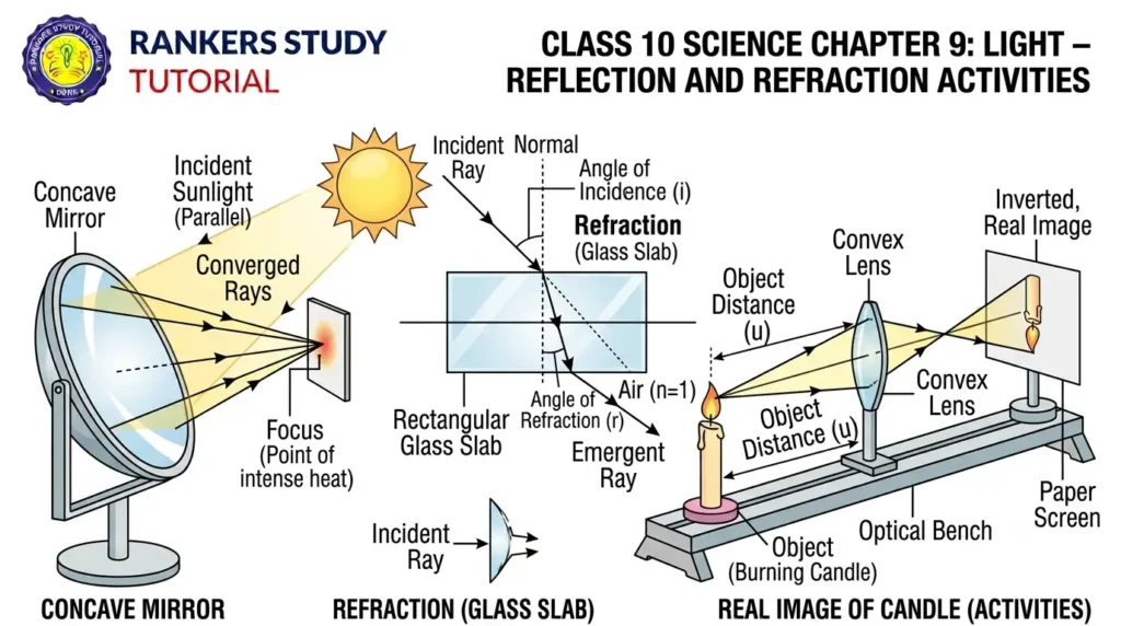
- Hold a concave mirror and direct its reflecting surface toward the distant Sun.
- Hold a paper sheet in front of the mirror and adjust its distance back and forth until a sharp, bright spot of light is obtained.
- Hold the mirror and paper steady in this position for a few minutes and observe.
Observations & Optical Mechanism
- Observation: The paper begins to smoke and eventually catches fire.
- Optical Mechanism: Sunlight consists of parallel rays that converge at the principal focus after reflection from a concave mirror, generating intense thermal concentration.
- Focal Length Estimation: The measured distance between the mirror pole and the sharp bright spot gives the approximate focal length (\(f\)) of the concave mirror.
Q1: Why does the paper sheet catch fire when placed at the focus of a concave mirror facing the Sun?
Answer: The concave mirror converges parallel sun rays onto a sharp focal point, concentrating solar thermal energy intensely enough to ignite the paper.
Q2: Define the principal focus of a concave mirror.
Answer: The principal focus of a concave mirror is a point on its principal axis where rays parallel to the principal axis meet or intersect after reflection from the mirror.
Q3 (Application Based): If the radius of curvature of a spherical mirror is 20 cm, what is its focal length?
Answer: Using the relation
\(f = \frac{R}{2}\)
, the focal length is \(20\text{ cm} / 2 = 10\text{ cm}\).Activity 9.3: Image Formation by a Concave Mirror
Mapping Object Positions and Screen Image Characteristics
Experimental Procedure
- Set up a concave mirror on a stand and mark reference lines corresponding to pole P, focus F, and centre C on a table.
- Place a burning candle beyond C and move a paper screen to capture a sharp image.
- Record nature, position, and relative size of the image.
- Repeat for object positions at C, between C and F, at F, and between P and F.
Observations & Optical Mechanism
- Real Images: Formed on the screen when the object is placed at or beyond F (inverted and real).
- Virtual Image: When placed between P and F, no screen image forms; an enlarged, erect virtual image is seen inside the mirror.
- Inference: Image characteristics vary systematically according to object distance relative to F and C.
Q1: Where should an object be placed in front of a concave mirror to obtain a real image of the exact same size as the object?
Answer: At the centre of curvature (C).
Q2: State the mirror formula relating object distance (\(u\)), image distance (\(v\)), and focal length (\(f\)).
Answer:
\(\frac{1}{v} + \frac{1}{u} = \frac{1}{f}\)
Q3 (Application Based): Write the expression for magnification (\(m\)) produced by a spherical mirror in terms of object and image heights or distances.
Answer:
\(m = \frac{h’}{h} = -\frac{v}{u}\)
Activity 9.4: Drawing Ray Diagrams for Concave Mirrors
Verifying Image Positions for All Object Locations
Experimental Procedure
- Draw neat ray diagrams for each position of the object corresponding to Table 9.1 (At infinity, Beyond C, At C, Between C and F, At F, Between P and F).
- Choose any two standard incident rays (parallel to principal axis, passing through F or C, or obliquely to P) to locate the image point.
- Compare the graphical results with experimental screen observations.
Observations & Optical Mechanism
- Ray Intersection: The intersection point of reflected rays determines the precise location, size, and nature of the image.
- Consistency: Graphical ray tracing matches the experimental screen findings across all object positions.
Q1: What happens to the position of the image formed by a concave mirror as the object is moved from infinity towards the pole?
Answer: The image moves progressively away from the focus towards infinity as the object approaches the mirror.
Q2 (Application Based): Where is the image formed if an object is placed at the principal focus (\(F\)) of a concave mirror?
Answer: At infinity, forming a highly magnified real image.
Activity 9.5: Image Formation by a Convex Mirror
Observing Pencil Images in a Convex Mirror
Experimental Procedure
- Hold a convex mirror in one hand and an upright pencil in the other.
- Observe the image of the pencil inside the convex mirror and check whether it is erect or inverted, diminished or enlarged.
- Slowly move the pencil away from the mirror and observe how the image size changes.
Observations & Optical Mechanism
- Image Nature: The image is always virtual, erect, and diminished regardless of the pencil’s distance.
- Size Variation: As the pencil is moved further away, the image becomes progressively smaller and moves closer to the focus behind the mirror.
Q1: What is the nature of the image formed by a convex mirror for any real object position?
Answer: Always virtual, erect, and diminished.
Q2 (Application Based): Why are convex mirrors used as security mirrors in department stores?
Answer: Because they provide an erect image and a very wide field of view.
Activity 9.6: Full-Length Images in Mirrors
Comparing Field of View and Full-Length Reflections of Distant Objects
Experimental Procedure
- Observe a distant tall object, such as a tree or building, in a plane mirror of varying sizes.
- Repeat the observation using a concave mirror and then a convex mirror.
- Determine which mirror successfully displays a full-length image of the tall object.
Observations & Optical Mechanism
- Plane Mirror: Can only show a full image if the mirror size is at least half the height of the object and placed at a suitable distance.
- Convex Mirror: Easily displays a full-length, erect, diminished image of a massive tall building due to its outward curvature and wide field of view.
Q1: Which type of spherical mirror is capable of forming a full-length diminished image of a tall distant building?
Answer: A convex mirror.
Q2 (Application Based): Where is a famous giant convex mirror installed in India to view the full Taj Mahal?
Answer: Fitted in a wall of the Agra Fort facing the Taj Mahal.
Activity 9.7: Picking up a Coin in Water
Attempting to Grab a Submerged Coin
Experimental Procedure
- Place a coin at the bottom of a bucket filled with water.
- Position your eye to the side above water and try to pick up the coin in one go.
- Note whether you succeeded on your first attempt.
Observations & Optical Mechanism
- Observation: Most people fail to pick up the coin in one go.
- Optical Mechanism: Light rays from the coin refract at the water-air interface, creating an apparent elevated position.
Q1: Why is it difficult to pick up a coin submerged in water on the first try?
Answer: Due to refraction, the coin appears raised above its actual position, tricking hand-eye coordination.
Q2 (Application Based): Does light travel faster in water or in air?
Answer: Light travels faster in air than in water, causing the apparent depth to be shallower than the real depth.
Activity 9.8: Reappearing Coin in a Bowl
Coin Visibility Upon Pouring Water into a Shallow Bowl
Experimental Procedure
- Place a coin in a shallow bowl and move away until the coin just disappears from sight.
- Have a friend pour water gently into the bowl without disturbing the coin.
- Keep looking from your fixed position and observe.
Observations & Optical Mechanism
- Observation: The coin becomes visible again when water is poured into the bowl.
- Optical Mechanism: Refraction bends light rays from the coin away from the normal as they enter the air, enabling them to reach an observer whose direct line of sight was previously blocked.
Q1: How does pouring water make a hidden coin visible again in Activity 9.8?
Answer: Refraction bends light rays from the coin upward at the water-air boundary, allowing rays to reach the observer’s eye from outside the direct straight-line obstruction.
Q2 (Application Based): What physical property of light is responsible for this phenomenon?
Answer: The change in direction (refraction) of light when traveling from an optically denser medium to a rarer medium.
Activity 9.9: Observing an Ink Line Through a Glass Slab
Apparent Elevation and Bending of Lines Through Thick Glass
Experimental Procedure
- Draw a thick straight ink line on a white paper sheet placed on a table.
- Place a glass slab over the line such that its edge makes an angle with the line, and observe from the sides.
- Reposition the slab normal to the line and view from the top.
Observations & Optical Mechanism
- Observation: The portion of the line beneath the glass slab appears raised and slightly bent at the edges when viewed obliquely.
- Inference: Refraction through parallel glass faces causes apparent vertical and lateral shifts in objects viewed through dense media.
Q1: Does the ink line appear bent when viewed normally (perpendicularly) through a glass slab?
Answer: No, it does not appear bent, but the portion under the slab appears noticeably raised toward the observer.
Q2 (Application Based): Why does printing under a thick glass slab appear elevated?
Answer: Refraction bends light rays away from the normal as they exit into the air, creating a virtual image closer to the upper surface.
Activity 9.10: Refraction through a Rectangular Glass Slab
Tracing Incident, Refracted, and Emergent Rays Across Parallel Glass Faces
Experimental Procedure
- Fix a white sheet on a board, place a rectangular glass slab in the middle, and outline its boundary (ABCD).
- Fix two pins (E and F) on an inclined line directed at the upper glass face.
- View pin images through the opposite face and align two more pins (G and H) in a straight line.
- Remove slab, trace ray paths, draw normals, and measure angles of incidence, refraction, and emergence.
Observations & Optical Mechanism
- Bending at Air-Glass Interface: Light bends towards the normal as it enters the denser glass medium.
- Bending at Glass-Air Interface: Light bends away from the normal as it re-enters the rarer air medium.
- Lateral Displacement: The emergent ray is parallel to the incident ray but undergoes a slight sideways shift because opposite faces have equal and opposite bending effects.
Q1: State Snell’s law of refraction.
Answer: The ratio of the sine of the angle of incidence to the sine of the angle of refraction is a constant for a given pair of media:
\(\frac{\sin i}{\sin r} = \text{constant}\)
Q2: How is the absolute refractive index (\(n_m\)) of a medium calculated using the speed of light?
Answer:
\(n_m = \frac{c}{v}\)
(where \(c\) is speed in air/vacuum and \(v\) is speed in medium)
Q3 (Application Based): Light enters from air into glass having a refractive index of 1.50. What is the speed of light in glass if the speed of light in vacuum is \(3 \times 10^8\text{ m s}^{-1}\)?
Answer: Using
\(v = \frac{c}{n}\)
, \(v = (3 \times 10^8\text{ m s}^{-1}) / 1.50 = 2 \times 10^8\text{ m s}^{-1}\).Activity 9.11: Focusing Sunlight with a Convex Lens
Igniting Paper with Solar Radiation via a Convex Lens
Experimental Procedure
- Hold a convex lens and direct it towards the distant Sun.
- Focus the light from the Sun onto a sheet of paper to obtain a sharp bright spot.
- Hold the paper and lens steady in this position and observe.
Observations & Optical Mechanism
- Observation: The paper begins to smoke and eventually catches fire.
- Optical Mechanism: Parallel solar rays converge at the principal focus of the convex lens, producing high thermal concentration.
Q1: Why does paper burn when placed at the focus of a convex lens facing the Sun?
Answer: The convex lens converges parallel sun rays onto a focal point, concentrating heat energy.
Q2 (Application Based): What does the distance between the convex lens and the bright spot on paper represent?
Answer: It gives the approximate focal length (\(f\)) of the convex lens.
Activity 9.12: Image Formation by a Convex Lens
Mapping Screen Images Across Various Object Distances from a Convex Lens
Experimental Procedure
- Set up a convex lens on a stand and mark reference lines for \(F_1\), \(2F_1\), \(F_2\), and \(2F_2\).
- Place a burning candle beyond \(2F_1\) and obtain a clear sharp image on a screen on the opposite side.
- Repeat for object positions at \(2F_1\), between \(F_1\) and \(2F_1\), at \(F_1\), and between \(F_1\) and optical centre \(O\).
Observations & Optical Mechanism
- Real vs Virtual: Real and inverted images form on the screen for objects beyond \(F_1\). A virtual erect image forms on the same side when placed within \(F_1\).
Q1: Where should an object be placed in front of a convex lens to get a real image of the same size?
Answer: At twice the focal length (\(2F_1\)).
Q2: State the lens formula relating object distance (\(u\)), image distance (\(v\)), and focal length (\(f\)).
Answer:
\(\frac{1}{v} – \frac{1}{u} = \frac{1}{f}\)
Q3 (Application Based): What type of lens is used as a magnifying glass by watchmakers?
Answer: A convex lens, when the object is placed within its focal length.
Activity 9.13: Image Formation by a Concave Lens
Observing Virtual and Diminished Images Through a Concave Lens
Experimental Procedure
- Take a concave lens and place it on a lens stand.
- Place a burning candle on one side of the lens and look through the other side.
- Attempt to capture the image on a screen, then observe directly through the lens.
- Move the candle away from the lens and note changes in image size.
Observations & Optical Mechanism
- Observation: No image can be caught on a screen because a concave lens produces a virtual image. When viewed directly, the image appears erect and diminished.
- Size Changes: As the candle is moved farther away, the virtual image becomes smaller and moves closer to the focus.
- Inference: A concave lens always gives a virtual, erect, and diminished image irrespective of the object position.
Q1: What is the nature of the image formed by a concave lens for any object position?
Answer: Always virtual, erect, and diminished.
Q2 (Application Based): A concave lens has a focal length of 15 cm. At what distance should an object be placed so it forms an image at 10 cm from the lens?
Answer: Using the lens formula
\(\frac{1}{v} – \frac{1}{u} = \frac{1}{f}\)
with \(v = -10\text{ cm}\) and \(f = -15\text{ cm}\), we get \(u = -30\text{ cm}\) (30 cm in front of the lens).