
Activity 12.1: Magnetic Effect of Current-Carrying Wire
Observing Compass Needle Deflection Near a Current-Carrying Conductor
Experimental Procedure
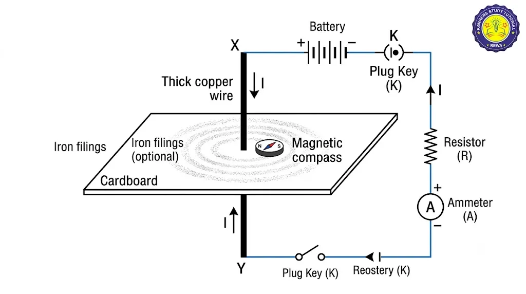
- Take a straight thick copper wire and place it between points \(X\) and \(Y\) in an electric circuit perpendicularly to the plane of paper.
- Horizontally place a small magnetic compass near the copper wire and note the initial position of its needle.
- Pass an electric current through the circuit by inserting the key into the plug.
- Observe the change or deflection in the position of the compass needle.
Observations & Optical Mechanism
- Needle Deflection: The compass needle gets deflected when current flows through the copper wire.
- Inference: An electric current-carrying wire produces a magnetic field around it, demonstrating that electricity and magnetism are linked.
Q1: What does the deflection of a compass needle near a current-carrying wire indicate?
Answer: It indicates that an electric current produces a magnetic field, showing a link between electricity and magnetism.
Q2 (Application Based): Who first accidentally discovered this relationship between electricity and magnetism in 1820?
Answer: Hans Christian Oersted.
Q3 (Additional Practice): What is a compass needle fundamentally composed of?
Answer: A small bar magnet.
Activity 12.2: Magnetic Field Lines Using Iron Filings
Visualizing Magnetic Fields Around a Bar Magnet
Experimental Procedure
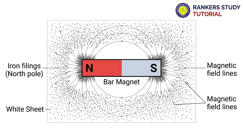
- Fix a sheet of white paper on a drawing board using adhesive material and place a bar magnet in its center.
- Sprinkle some iron filings uniformly around the bar magnet using a salt-sprinkler.
- Gently tap the drawing board and observe the resulting pattern.
Observations & Optical Mechanism
- Filing Pattern: Iron filings arrange themselves in distinct curved patterns along lines surrounding the bar magnet.
- Magnetic Field: The region where the magnetic force is detected represents the magnetic field, and the alignment lines represent magnetic field lines.
Q1: Why do iron filings arrange themselves in a specific pattern around a bar magnet?
Answer: Because the magnet exerts an magnetic influence and force in the surrounding region, causing the filings to experience a mechanical force and align.
Q2 (Application Based): What do the lines along which iron filings align represent?
Answer: Magnetic field lines.
Activity 12.3: Drawing Magnetic Field Lines of a Bar Magnet
Mapping Field Lines Using a Small Compass Needle
Experimental Procedure
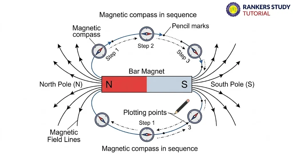
- Fix a white paper sheet on a board with a bar magnet in the center and trace its boundary.
- Place a small compass near the north pole and mark the positions of the two ends of the needle.
- Move the needle step-by-step so that its south pole occupies the position previously occupied by its north pole, proceeding until the south pole is reached.
- Join the marked points with a smooth curve to map the field line.
Observations & Optical Mechanism
- Field Direction: Magnetic field lines emerge from the north pole and merge at the south pole outside the magnet, forming closed curves.
- Field Strength: Field lines are crowded near the poles where the magnetic field is strongest.
Q1: What is the direction of magnetic field lines inside a bar magnet?
Answer: From its south pole to its north pole.
Q2 (Application Based): Why do no two magnetic field lines ever cross each other?
Answer: If they intersected, it would mean the compass needle points towards two different directions at the same point, which is impossible.
Activity 12.4: Direction of Magnetic Field Due to Current
Observing Deflection Reversal with Current Direction
Experimental Procedure
- Connect a long straight copper wire, cells, and a plug key in series.
- Place the straight wire parallel to and over a compass needle and plug the key.
- Observe the direction of deflection of the north pole when current flows from north to south.
- Reverse the cell connections to reverse the current direction from south to north and note the needle movement.
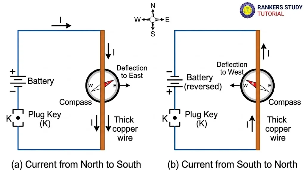
Observations & Optical Mechanism
- Deflection Reversal: Reversing the current direction causes the compass needle to deflect in the opposite direction.
- Inference: The direction of the magnetic field produced by an electric current depends directly on the direction of current flow.
Q1: What happens to the deflection of the compass needle when the direction of current through the wire is reversed?
Answer: The direction of deflection is reversed (moves in the opposite direction).
Q2 (Application Based): What does this reversal indicate about the generated magnetic field?
Answer: It indicates that the direction of the magnetic field produced by the electric current is also reversed.
Activity 12.5: Magnetic Field Around a Straight Conductor
Concentric Circle Field Lines Around a Straight Current-Carrying Wire
Experimental Procedure
- Insert a long straight thick copper wire vertically through the center of a rectangular cardboard fixed horizontally.
- Connect the wire in series with a battery, variable resistance, ammeter, and plug key.
- Sprinkle iron filings uniformly on the cardboard, close the key, and gently tap the board.
- Observe the pattern formed by the filings and check field direction using a small compass.
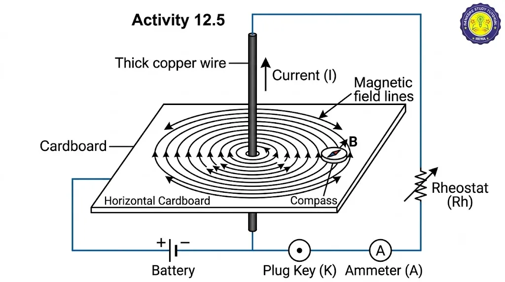
Observations & Optical Mechanism
- Concentric Circles: Iron filings align themselves in a pattern of concentric circles around the copper wire.
- Distance and Magnitude: Deflection decreases as the compass moves away from the wire; circles become larger, showing magnetic field decreases with distance. Increasing current increases field magnitude.
Q1: What do the concentric circles formed by iron filings around a straight current-carrying wire represent?
Answer: Magnetic field lines.
Q2: State the right-hand thumb rule.
Answer: If you hold a straight current-carrying conductor in your right hand with the thumb pointing towards the current, your fingers wrap around in the direction of the magnetic field lines.
Q3 (Application Based): How does the magnitude of the magnetic field change when the current through the wire is increased?
Answer: The magnitude of the magnetic field increases (indicated by greater needle deflection).
Activity 12.6: Magnetic Field of a Circular Coil
Magnetic Field Patterns Produced by a Current-Carrying Circular Coil
Experimental Procedure
- Take a rectangular cardboard with two holes and insert a circular coil having a large number of turns normally through them.
- Connect the coil ends in series with a battery, key, and rheostat.
- Sprinkle iron filings uniformly on the cardboard, plug the key, and tap gently.
- Observe the resulting pattern of the iron filings.
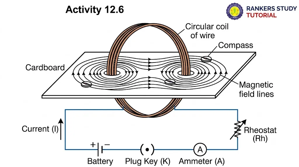
Observations & Optical Mechanism
- Arc Straightening: Near the wire, concentric circles appear; at the center of the circular loop, the arcs appear as straight lines.
- Turn Multiplicity: For a coil with \(n\) turns, the magnetic field is \(n\) times as large as a single turn since individual fields add up.
Q1: What shape do the magnetic field lines take near the center of a current-carrying circular loop?
Answer: They appear as straight lines.
Q2 (Application Based): Why is the magnetic field produced by a coil with \(n\) turns stronger than a single-turn loop?
Answer: Because the current in each turn flows in the same direction, causing the magnetic fields of all turns to add up.
Activity 12.7: Force on a Current-Carrying Conductor in Magnetic Field
Mechanical Displacement of a Conductor in a Magnetic Field
Experimental Procedure
- Suspend a small aluminum rod AB horizontally using two connecting wires from a stand.
- Place a strong horseshoe magnet so the rod lies between its poles with the magnetic field directed upwards.
- Connect the rod in series with a battery, key, and rheostat, and pass current from end B to end A.
- Observe the displacement direction of the rod, then reverse the current or magnetic field poles.
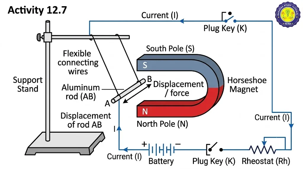
Observations & Optical Mechanism
- Rod Displacement: The current-carrying rod experiences a mechanical force perpendicular to its length and the magnetic field, causing it to displace.
- Direction Rule: Reversing current or magnetic field poles reverses the force direction (Fleming’s left-hand rule). Maximum force occurs when current and field are mutually perpendicular.
Q1: State Fleming’s left-hand rule.
Answer: Stretch the thumb, forefinger, and middle finger of your left hand mutually perpendicular. If the forefinger points in the direction of the magnetic field and the middle finger in the direction of current, the thumb points in the direction of motion or force.
Q2 (Application Based): Under what condition is the force experienced by a current-carrying conductor in a magnetic field the largest?
Answer: When the direction of current is at right angles (perpendicular) to the direction of the magnetic field.
Q3 (Additional Practice): Name devices that operate on the principle of current-carrying conductors experiencing force in magnetic fields.
Answer: Electric motors, electric generators, loudspeakers, microphones, and measuring instruments.
Core Concepts: Solenoids, Electromagnets & Domestic Circuits
Solenoid Properties, Electromagnets, and Household Wiring Standards
Solenoids & Electromagnets
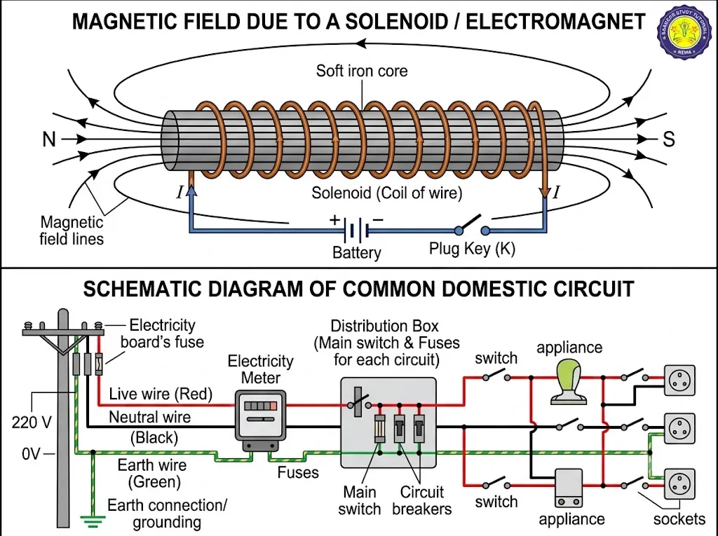
- Solenoid: A coil of many circular turns of insulated copper wire wrapped closely as a cylinder; its magnetic field pattern is identical to a bar magnet.
- Uniform Field: Field lines inside a solenoid are parallel straight lines, indicating a uniform magnetic field at all points inside.
- Electromagnet: A strong magnetic field inside a solenoid used to magnetize soft iron or steel cores.
Domestic Electric Circuits & Safety
- Supply Standards: In India, we receive AC power of \(220\text{ V}\) with a frequency of \(50\text{ Hz}\). Live wire has red insulation, neutral wire has black insulation, and earth wire has green insulation.
- Parallel Connection: All domestic appliances are connected in parallel to ensure equal potential difference and independent operation.
- Safety Devices: Earth wire prevents severe shocks from metallic body leakage; fuses melt via Joule heating to prevent damage during short-circuiting or overloading.
Q1: What is a solenoid, and how does its internal magnetic field behave?
Answer: A solenoid is a cylindrical coil of insulated copper wire. Its internal field lines are parallel straight lines, signifying a uniform magnetic field.
Q2: What is short-circuiting, and how does a fuse prevent damage?
Answer: Short-circuiting occurs when live and neutral wires come into direct contact, causing current to increase heavily. A fuse melts due to Joule heating, breaking the circuit and stopping current flow.
Q3 (Application Based): What is the function of the green-insulated earth wire in domestic appliances?
Answer: It connects metallic bodies deep into the earth to provide a low-resistance path, keeping potential at earth level and preventing severe shocks.
Q4 (Additional Practice): Why are appliances connected in parallel rather than in series in household circuits?
Answer: So that each appliance receives the identical potential difference (\(220\text{ V}\)) and can be switched ON/OFF independently without affecting others.
Q5 (Advanced Mastery): What causes overloading in a domestic circuit?
Answer: Overloading can happen due to direct contact of live and neutral wires (short circuit), an accidental hike in supply voltage, or connecting too many appliances to a single socket.