Hint: Draw magnetic field lines for a bar magnet, in order to identify the magnetic field strength at different points around a magnet.
Question.1. A student learns that magnetic field strength around a bar magnet is different at every point. Which diagram shows the correct magnetic field lines around a bar magnet?
(a) 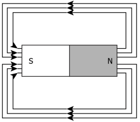

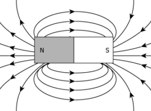
Question.2. A student places some iron fillings around a magnet. The iron fillings arrange themselves as shown in image. 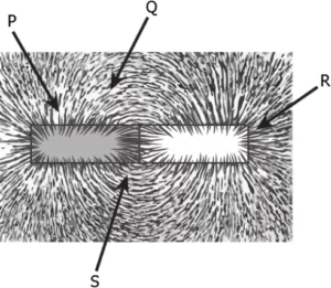
(a) P
(b) Q
(c) R
(d) S
Ans.1. (c) 
Hint: Represent magnetic field lines for a straight current carrying conductor, in order to identify the magnetic field strength at different points around it.
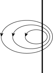
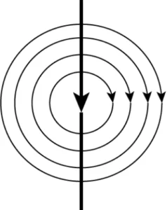
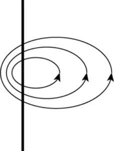
Question.3. A student placed a magnetic compass around a straight current carrying wire. The student noticed when he moved the compass away from the wire, the deflection in compass decreases. How would be the magnetic field lines around the conductor?
(a) 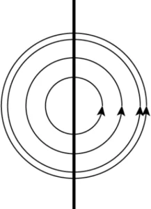
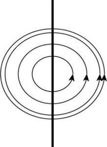
Question.4. The image shows the magnetic field lines around a straight current carrying conductor.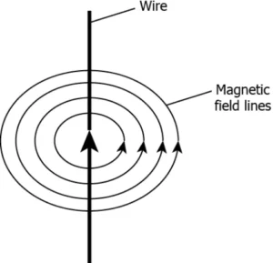
(a) 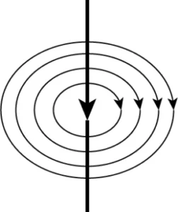
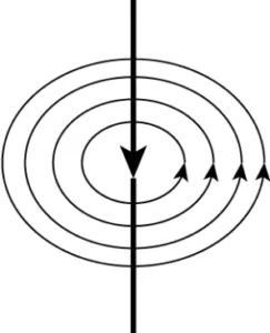
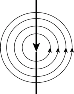
Ans.3. (b) 
Hint: Draw magnetic field lines for at current carrying circular loop, in order to identify the magnetic field strength at different points around it.
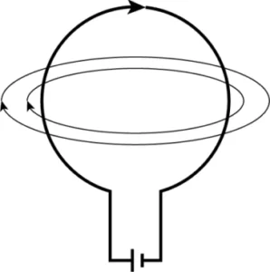
Question.5. Which diagram shows the magnetic field lines around a current carrying circular loop?
(a) 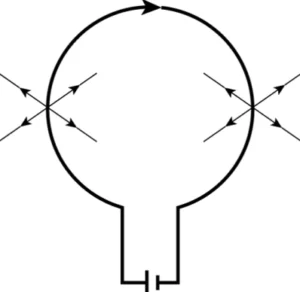
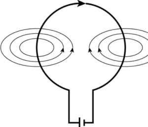
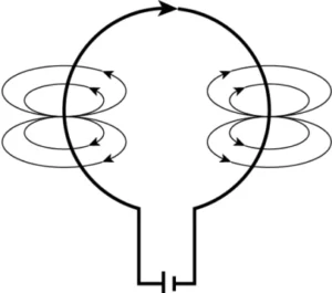
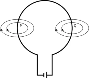
Question.6. Which diagram shows the correct direction of the magnetic field lines at point P and Q in current carrying circular loop?
(a) 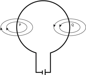
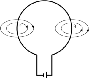
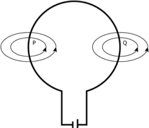
Ans.5. (b) 
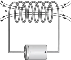
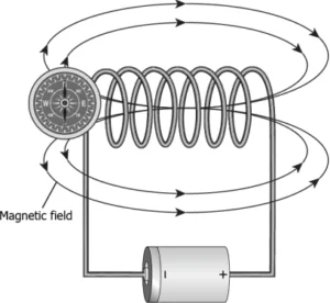
Hint: Outline magnetic field lines for at current carrying solenoid, in order to identify the magnetic field strength at different points around it.
Question.7. The magnetic field lines of solenoid are similar to the magnetic field lines of bar magnet. Which image correctly shows the solenoid as a bar magnet?
(a) 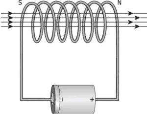
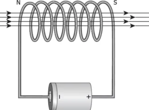
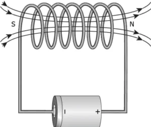
Question.8. Where should the magnetic compass be placed in solenoid to get maximum deflection in the magnetic compass?
(a) 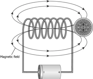
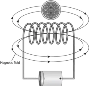
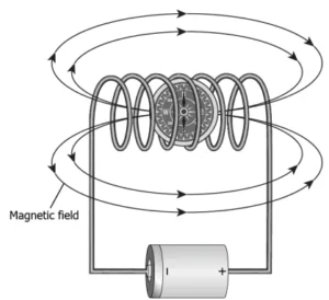
Ans.7. (c) 
Hint: State Fleming’s left-hand rule, in order to understand the working of an electric motor.
Question.9. The image shows the Fleming’s left-hand rule.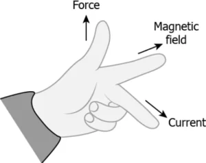
(a) When a current carrying conductor is moved with a force, it creates the magnetic field.
(b) When a conductor is moved inside a magnetic field, current is produced in the conductor.
(c) When magnetic field is moved relative to the conductor, current is produced in the conductor.
(d) When a current carrying conductor placed in a magnetic field, it experiences a force by magnetic field.
Question.10. A metal rod PQ is placed in the magnetic field. The ends of the rod are connected with a battery using wires.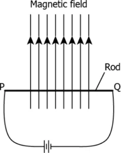
(a) upward
(b) downwards
(c) into the field
(d) out of the field
Ans.9. (d) When a current carrying conductor placed in a magnetic field, it experiences a force by magnetic field.
Ans.10. (d) out of the field
Hint: Discuss electromagnetic induction, in order to understand how a moving magnet can be used to generate electric currents.
Question.11. A student inserts a bar magnet in the coil. The student observes deflection in the galvanometer connected to the coil. What will happen if the magnet is continuously getting in and out of the coil?
(a) the current induced in the coil will increase
(b) the current will change its direction continuously
(c) the magnetic field will create a motion in the coil
(d) the magnetic field of the bar magnet would keep decreasing
Question.12. A student makes an arrangement to study electromagnetic induction, as shown.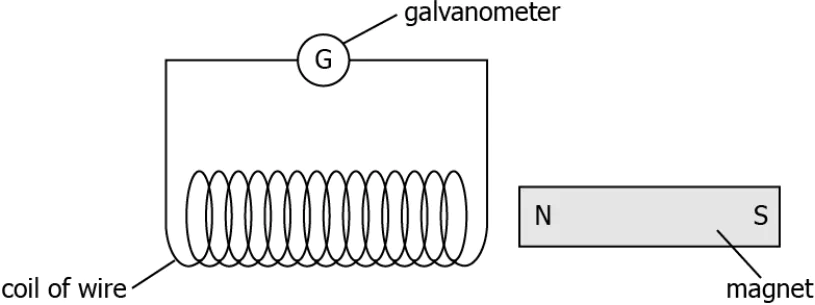
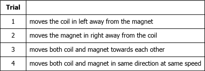
(a) trial 1
(b) trial 2
(c) trial 3
(d) trial 4
Ans.11. (b) the current will change its direction continuously
Ans.12. (d) trial 4
Hint: Explain Fleming’s right-hand rule, in order to understand the working of an electric generator.
Question.13. The image shows the components of an electric generator. When the coil PQRS is rotated as shown.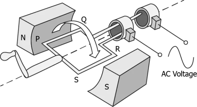
(a) PQ: Q to P; RS: R to S
(b) PQ: P to Q; RS: R to S
(c) PQ: P to Q; RS: S to R
(d) PQ: Q to P; RS: S to R
Question.14. A force is applied to a wire inside a horse show a magnet. The current induced in the wire as shown.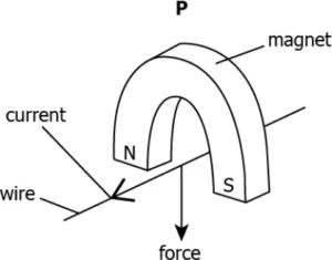
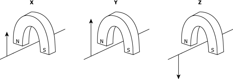
(a) only X
(b) only Y
(c) both X and Y
(d) both Y and Z
Ans.13. (b) PQ: P to Q; RS: R to S
Ans.14. (a) only X
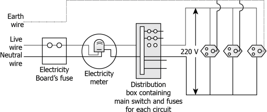
Hint: Analyse the significance of neutral, earth and live wire, in order to understand formation of a domestic electrical circuit.
Question.15. Appliances that have metal body are generally connected to the earthing wire. What is the reason to earth these wires?
(a) to prevent excess of current
(b) to prevent the leakage of current
(c) to provide extra current to appliance
(d) to provide high resistance to the appliance
Question.16. Which diagram shows the domestic electric circuit?
(a) 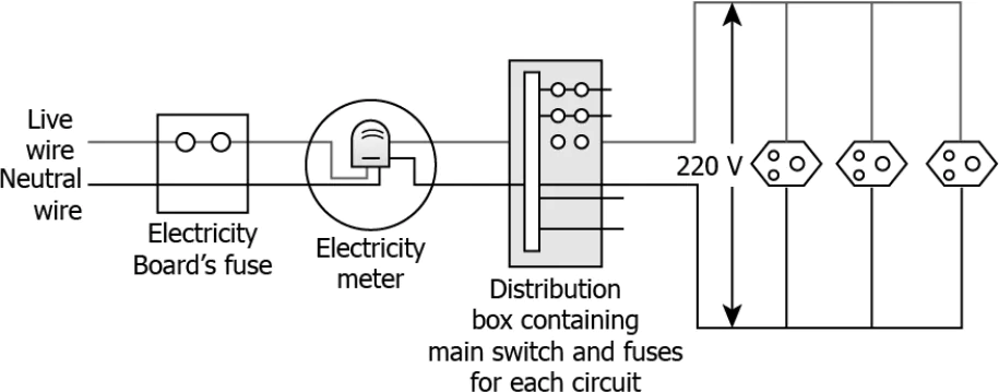
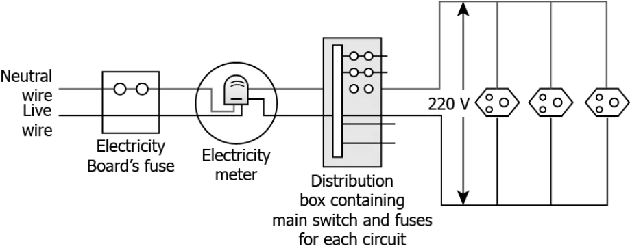
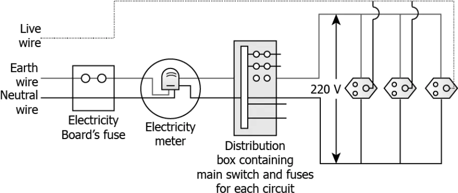
Ans.15. (b) to prevent the leakage of current
Ans.16. (d)
